CHECK OUT OUR PROMOTIONS HERE
Category 1 Short Name4
Category 1.1 Short Name35123
Hieu's Categori 1
Hieu's Categori 11
Hieu Catyeogi Test 32
Hieu's Categori 2
Hieu's Categori 3
Hieu's Categori 4
Hieu's Categori 5
Test 1 duy anh test
Test 1.1
Hieu's Category 2
Hieu's Category 3
Hieu's Category 4
Hieu's Category 5
Hanh Test CWC 2
2.2 Test
Hanh Test CWC 3_Update
Test 3.1
Test 3.1.1
Test 3.1.1.2
Hanh Test CWC 4
Hanh Test CWC 5_Update
Test 5.1
Test 5.1.2
Hanh Test CWC 6
Test 6.1
Test 6.1.2
Test 6.2
Test 6.2.1
Hanh Test CWC 4_05/03/2026
Hanh Test CWC 7 lan 36
Hanh Test 7.1
Test 7.1.1
Test 7.1.2 v2v2v2v2
Hanh Test CWC 9
| Table 1 | |
|---|---|
| Physical Properties of PVC Jacket | |
| Unaged Tensile Strength, minimum (PSI) 1500 | |
| Aged* Tensile Strength, minimum retention (%) 85 | |
| Unaged Elongated, minimum (%) 100 | |
| Aged* Elongated, minimum retention (%) 60 | |
| Heat Distortion 1 hr at 121 ºC, maximum (%) 50 |
*Aged for 120 hrs at 100 ºC
| Temperature Rating | |
|---|---|
| Insulated Conductor and Copper Tape Shield Temperature Ratings | |
| Normal: | 105 ºC |
| Emergency*: | 140 ºC |
| Short-Circuit – Insulated Conductor: | 250 ºC |
| Short-Circuit – Copper Tape Shield: | 200 ºC |
*Operation at the emergency overload temperature shall not exceed 1500 hours cumulative during the lifetime of the cable.
| Standards | |
|---|---|
| ASTM B400 – Compact Round Concentric-Lay-Stranded Aluminum 1350 Conductors | |
| ICEA S-97-682 – Utility Shielded Power Cables Rated 5 Through 46 kV | |
| ICEA T-31-610 – Test Method for Conducting Longitudinal Water Penetration Resistance Tests on Blocked Conductors | |
| ICEA T-34-664 – Test Method for Conducting Longitudinal Water Penetration Resistance Tests on Longitudinal Water Blocked Cables | |
| ICEA P-45-482 – Short Circuit Performance of Metallic Shields and Sheaths on Insulated Cable | |
| AEIC CS8 – Extruded Dielectric, Shielded Power Cables Rated 5 Through 46 kV | |
| UL 1072 – Medium-Voltage Power Cables |
| Country | |
|---|---|
| USA |
12-Jul-21
| Image | |
|---|---|
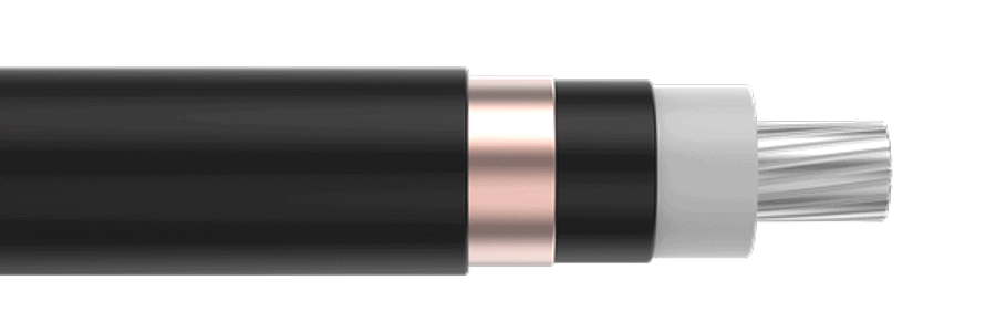
| MV AL XLPE CTS |